Generic firmware
» Documentation | Development | Issues | Source code | README
Tip
Please continue reading this document on our documentation space, all inline links will be working there.
About
A flexible software breadboard for sensor-, relay-, and gateway-nodes, transmitting telemetry data in multi-hop radio link environments. It is a hybrid/unified single-file firmware generic.ino, with an accompanying configuration settings header file, config.h.
The system has originally been conceived for beehive monitoring, but can be used for other environmental monitoring purposes.
Hardware
The firmware has been primarily conceived for MCUs of the AVR microcontroller family, specifically the Atmel ATmega328 (now Microchip), in form of the vanilla Arduino Uno, the JeeLink v3c, and with a spin-off to the LinkIt Smart 7688 Duo.
For sensor hardware, it uses the usual suspects HX711, DS18B20, and DHT22, for weight-, temperature-, and humidity-measurements.
Software
The telemetry subsystem is based on the excellent RFM69, RadioHead, and BERadio C++ libraries.
Synopsis
Multi-hop RF / ISM / packet radio and telemetry yak shaving.
![// Synopsis of the Hiveeyes generic firmware
digraph generic_firmware_synopsis {
// Options
rankdir=LR;
ranksep=0.5;
// Style
//graph [splines=ortho];
node [pin=true, shape="box", fontname="Verdana"];
edge [fontname="Verdana"];
// Graph nodes represent hardware node units
"sensor-1" [label="Sensor node 1"];
"sensor-2" [label="Sensor node 2"];
"sensor-N" [label="Sensor node N"];
"relay" [label="Telemetry relay node"];
"gateway" [label="Gateway node"];
"soc" [label="SoC machine", style=dashed];
// Graph edges represent radio families and
// protocols spoken between node units.
"sensor-1" -> "relay" [label="RFM69"];
"sensor-2" -> "relay";
"sensor-N" -> "relay";
"relay" -> "gateway" [label="RFM95\n(LoRa)"];
"gateway" -> "soc" [label="UART", style=dashed];
// Draw a dotted line between sensor-2
// and sensor-N, but retain node positions.
"sensor-2" -> "sensor-N" [dir=none, style=dotted];
{rank=same; "sensor-1"; "sensor-2"; "sensor-N" };
}](../../_images/graphviz-9e2e7cfc07c1b988f5b7a54ae7b4929a85f39d9e.png)
The firmware serves different purposes, you can configure it as a »sensor node«, »telemetry relay node«, or »network gateway node«.
A sensor node collects sensor data, encodes it using BERadio, and sends it through a RFM69 radio module directly to a network gateway node, or to an intermediary telemetry relay node.
A telemetry relay node receives radio signals on RFM69 and emits them to RFM95 (LoRa). The messages are processed opaque, no decoding takes place here.
The network gateway node receives RFM95 (LoRa) radio signals and emits the message payloads to its UART interface connected to the gateway computer.
The gateway computer, for example a Linux machine like the Raspberry Pi, is running the BERadio forwarder application. It will decode the data according to the BERadio specification, and forward it to the TCP/IP network using the MQTT protocol, serialized as JSON dictionary.
Workbench
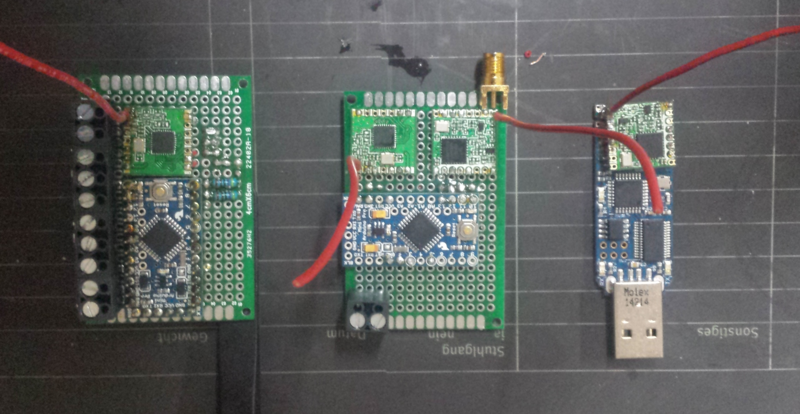
Three nodes, each running the “generic” firmware in a different configuration. A »sensor node« emitting telemetry data via RFM69 (left), a »telemetry relay node« receiving RFM69 and emitting RFM95 LoRa (middle), and a »network gateway node« receiving RFM95 LoRa and sending it to the UART interface (right), effectively plugged into a Linux computer’s USB port.
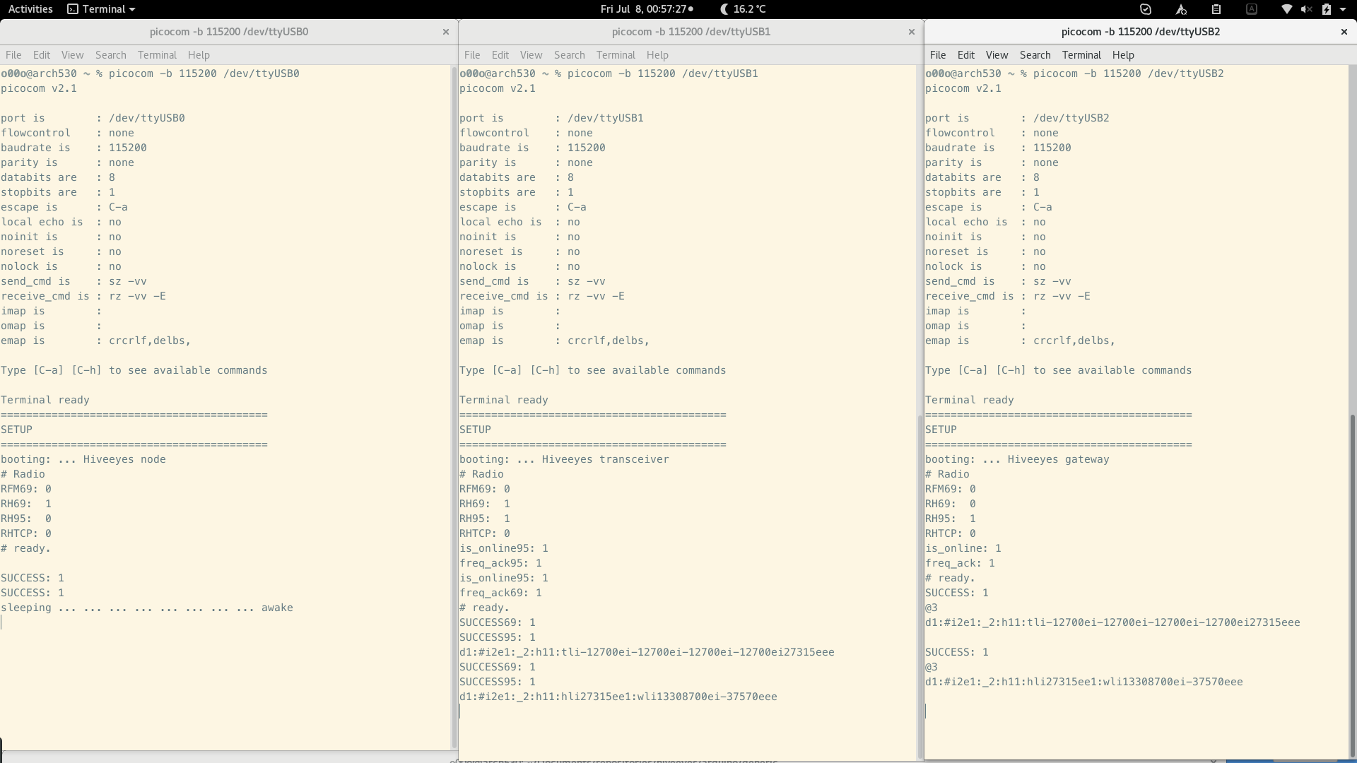
Three picocom instances connected to each of the three networked nodes.
Usage
Build on your workstation
# Acquire the source code repository including all dependencies.
git clone https://github.com/hiveeyes/arduino

# Select this firmware.
cd generic

# Build firmware.
make build

# Upload to MCU.
make upload
Tip
Please inspect the platformio.ini file, and adjust it to match your setup.
Configuration
In order to configure and build the firmware for different operation modes (node vs.
relay vs. gateway), the PlatformIO configuration file platformio.ini
provides corresponding environment sections, which you can adjust to your needs.
Try those commands to invoke builds for the individual target environments:
# Activate Python virtualenv, where your PlatformIO installation lives.
source .venv/bin/activate

# Run build for individual environments.
pio run --environment=node-rfm69
pio run --environment=node-rh69
pio run --environment=relay
pio run --environment=gateway-rh69
pio run --environment=gateway-rh95
pio run --environment=gateway-rh95-linkit7688
In order to adjust individual build flags for your setup, we recommend to add a custom
environment section to the platformio.ini file. Alternatively, you can build with
a custom configuration settings header file, using the -D CUSTOM_CONFIG=config_foobar.h
directive.
You can also invoke the build by defining build_flags on the command line, like:
PLATFORMIO_BUILD_FLAGS="-D CUSTOM_CONFIG=config_foobar.h" pio run --environment=relay